A modern technology banner image

1.Automatic water level controller

OBJECTIVE

To simulate a water level controller in Wokwi that automatically or manually controls the motor based on tank water levels, helping to save water and prevent overflow.

MODULES REQUIRED

  • Arduino uno
  • Ultrasonic sensor
  • Potentiometer
  • Push button
  • Resistor 1k
  • Led
  • Slide switch
  • DPDT Relay

SCHEMATIC DIAGRAM

Schematic diagram showing an Arduino connected to an LED and a push button.

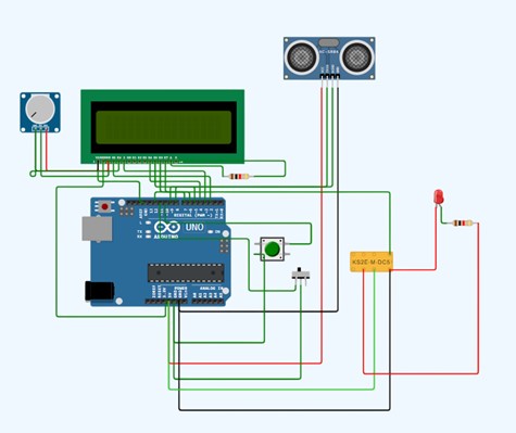
SCHEMATIC CONNECTION

Connect potentiometer:

  • Connect the Gnd pin of the potentiometer to the RW pin on the Lcd.
  • Connect the Sig pin of the potentiometer to the V0 pin on the Lcd.
  • Connect the VCC pin of the potentiometer to the VDD pin on the Lcd .
  • Connect LCD :

  • Connect the Vs pin of the Lcd to the Gnd pin on the Arduino.
  • Connect the VDD pin of the Lcd to the 5V pin on the Arduino
  • Connect the RS pin of the Lcd to the D2 pin on the Arduino.
  • Connect the E pin of the Lcd to the D3 pin on the Arduino.
  • Connect the D4 pin of the Lcd to the D4 pin on the Arduino.
  • Connect the D5 pin of the Lcd to the D5 pin on the Arduino.
  • Connect the D6 pin of the Lcd to the D6 pin on the Arduino .
  • Connect the D7 pin of the Lcd to the D7 pin on the Arduino .
  • Connect the K pin of the Lcd to the GND pin on the Arduino .
  • Connect the A pin of the Lcd to the 5V pin on the Arduino .
  • connect the A pin to one end of the resistor and the other end of the resistor to the Lcd VDD pin.
  • Connect ultrasonic sensor :

  • Connect the vcc pin of the ultrasonic sensor to the 5V pin on the Arduino.
  • Connect the Trig pin of the ultrasonic sensor to the D8 pin on the Arduino.
  • Connect the Echo pin of the ultrasonic sensor to the D9 pin on the Arduino.
  • Connect the Gnd pin of the ultrasonic sensor to the Gnd pin on the Arduino.
  • Connect push button:

  • Connect the +ve pin of the push button to the D10 pin on the Arduino.
  • Connect the -ve pin of the push button to the Gnd pin on the Arduino.
  • Connect switch:

  • Connect the +ve pin of the switch to the D11 pin on the Arduino
  • Connect the -ve pin of the switch to the Gnd pin on the Arduino.
  • Connect Dpdt relay:

  • Connect the coil 2 of the Relay to the D12 pin on the Arduino.
  • Connect the coil 1 of the Relay to the Gnd pin on the Arduino.
  • Connect the led Anode to one end of the Resistor and the other end of the Resistor to the NC1 pin on the Relay .
  • Connect the Led cathode to the coil 1 pin on the relay.
  • To begin your project, click this template link:

    Simulate on Wokwi

    ARDUINO CODE

    
     #include (EEPROM.h)
    
    #include (LiquidCrystal.h)
    LiquidCrystal lcd(2,3,4,5,6,7);
    
    long duration, inches;
    int set_val,percentage;
    bool state,pump;
    
    void setup() {
      
      lcd.begin(16, 2);
      lcd.print("WATER LEVEL:");
      lcd.setCursor(0, 1); 
      lcd.print("PUMP:OFF MANUAL");
      
      pinMode(8, OUTPUT);
      pinMode(9, INPUT);
      pinMode(10, INPUT_PULLUP);
      pinMode(11, INPUT_PULLUP);
      pinMode(12, OUTPUT);
      
       set_val=EEPROM.read(0);
       if(set_val>150)set_val=150;
    }
    void loop() {
      
       digitalWrite(3, LOW);
       delayMicroseconds(2);
       digitalWrite(8, HIGH);
       delayMicroseconds(10);
       digitalWrite(8, LOW);
       duration = pulseIn(9, HIGH);
       inches = microsecondsToInches(duration);
       
       percentage=(set_val-inches)*100/set_val;
       
       lcd.setCursor(12, 0); 
       if(percentage<0)percentage=0;
       lcd.print(percentage);
       lcd.print("%   ");
        
       if(percentage<30&digitalRead(11))pump=1;
       if(percentage>99)pump=0;
       digitalWrite(12,!pump);
         
       lcd.setCursor(5, 1);
       if(pump==1)lcd.print("ON ");
       else if(pump==0) lcd.print("OFF");
       
        lcd.setCursor(9, 1);
        if(!digitalRead(11))lcd.print("MANUAL");
        else lcd.print("AUTO   ");
        
        if(!digitalRead(10)&!state&digitalRead(11)){
          state=1;
          set_val=inches;
          EEPROM.write(0, set_val);
          }
          
         if(!digitalRead(10)&!state&!digitalRead(11)){
            state=1;
            pump=!pump;
         
          }
          
        if(digitalRead(10))state=0;
          
        
        delay(500);
    }
    long microsecondsToInches(long microseconds) {
       return microseconds / 74 / 2;
    }


    INSTRUCTIONS

  • Assemble the circuit by connecting all components as shown in the schematic diagram.
  • On the left side of the screen, open sketch.ino and write your Arduino code.
  • After completing the circuit and writing the code, click the green Play button to start the simulation.
  • The controller uses sensors and an Arduino to automatically or manually turn the motor ON or OFF based on the tankโ€™s water level.
  • WORKING PRINCIPLE

  • The system uses sensors to detect water levels and controls a motor via an Arduino . It runs automatically based on tank levels or manually through a switch, with all logic coded and tested in the simulation.

  • Project Link

    for your reference.

    `