
Traffic signal with countdown, four-digit
OBJECTIVE
To determine the traffic control is managed by counting down the time for each basic traffic light signal (red, yellow, and green).
MODULES REQUIRED
- Arduino uno
- 4 digit display
- Resistor 220Ω
- Green Led
- Red led
- Yellow led
SCHEMATIC DIAGRAM
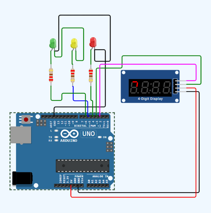
SCHEMATIC CONNECTION
Connect 4 digit display:
Connect Green LED :
Connect Yellow LED :
Connect RED LED :
To begin your project, click this template link:
ARDUINO CODE
#include (TM1637Display.h)

// Define the pins for the 4-digit display (TM1637 module)
#define CLK 2
#define DIO 3

// Create an instance of the display
TM1637Display display(CLK, DIO);

// Define pins for red, yellow, and green LEDs
#define RED_LED 4
#define YELLOW_LED 5
#define GREEN_LED 6

// Define the time intervals for each light
#define GREEN_LIGHT_DURATION 5000 // 5 seconds
#define YELLOW_LIGHT_DURATION 3000 // 3 seconds
#define RED_LIGHT_DURATION 7000 // 7 seconds

unsigned long previousMillis = 0;
int light = 1;
int remainingTime = 0;

void setup() {
  // Set pins as OUTPUT
  pinMode(RED_LED, OUTPUT);
  pinMode(YELLOW_LED, OUTPUT);
  pinMode(GREEN_LED, OUTPUT);

  // Initialize the 4-digit display
  display.setBrightness(7); // Adjust the brightness (0-7)
}

void loop() {
  unsigned long currentMillis = millis();

  switch (light) {
    case 1: // Green light
      digitalWrite(RED_LED, LOW);
      digitalWrite(YELLOW_LED, LOW);
      digitalWrite(GREEN_LED, HIGH);
      if (remainingTime > 0) {
        if (currentMillis - previousMillis >= 1000) {
          remainingTime--;
          previousMillis = currentMillis;
        }
      } else {
        light = 2; // Switch to yellow light
        remainingTime = 3;
        previousMillis = currentMillis;
      }
      break;
    case 2: // Yellow light
      digitalWrite(RED_LED, LOW);
      digitalWrite(YELLOW_LED, HIGH);
      digitalWrite(GREEN_LED, LOW);
      if (remainingTime > 0) {
        if (currentMillis - previousMillis >= 1000) {
          remainingTime--;
          previousMillis = currentMillis;
        }
      } else {
        light = 3; // Switch to red light
        remainingTime = 7;
        previousMillis = currentMillis;
      }
      break;
    case 3: // Red light
      digitalWrite(RED_LED, HIGH);
      digitalWrite(YELLOW_LED, LOW);
      digitalWrite(GREEN_LED, LOW);
      if (remainingTime > 0) {
        if (currentMillis - previousMillis >= 1000) {
          remainingTime--;
          previousMillis = currentMillis;
        }
      } else {
        light = 1; // Switch to green light
        remainingTime = 5;
        previousMillis = currentMillis;
      }
      break;
  }

  // Display the remaining time on the 4-digit display
  display.showNumberDecEx(remainingTime, 0b01000000, true);
}