
Distance-Based Traffic Control Using Arduino and Ultrasonic Sensors
OBJECTIVE
This project aims to control traffic flow using Arduino by detecting vehicle distances with ultrasonic sensors. Based on proximity, LEDs and an I2C LCD display provide real-time alerts to enhance road safety.
MODULES REQUIRED
- Arduino uno
- Led (Red & Green)
- 2 x ultrasonic sensors
- Lcd 16 x2 I2C
- Resistor 220 Ω
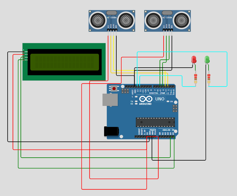
SCHEMATIC DIAGRAM
SCHEMATIC CONNECTION
Connection LCD :
Connect ultrasonic sensor :
Connect ultrasonic sensor2:
Connect leds :
To begin your project, click this template link:
ARDUINO CODE
#include (Wire.h)
#include (LiquidCrystal_I2C.h)

// Set the LCD address to 0x27 for a 16 chars and 2 line display
LiquidCrystal_I2C lcd(0x27, 16, 2);

// Ultrasonic sensor pins
const int trigPin1 = 2;
const int echoPin1 = 3;
const int trigPin2 = 4;
const int echoPin2 = 5;

// LED pins
const int redLED = 12;
const int greenLED = 13;

long duration1, distance1;
long duration2, distance2;

void setup() {
  lcd.init();               // Initialize the LCD
  lcd.backlight();          // Turn on the backlight
  pinMode(trigPin1, OUTPUT);
  pinMode(echoPin1, INPUT);
  pinMode(trigPin2, OUTPUT);
  pinMode(echoPin2, INPUT);
  pinMode(redLED, OUTPUT);
  pinMode(greenLED, OUTPUT);
  lcd.print("Distance Sensor");
  delay(2000);
  lcd.clear();
}

void loop() {
  distance1 = getDistance(trigPin1, echoPin1);
  distance2 = getDistance(trigPin2, echoPin2);

  lcd.setCursor(0, 0);
  lcd.print("L:");
  lcd.print(distance1);
  lcd.print("cm ");

  lcd.setCursor(8, 0);
  lcd.print("R:");
  lcd.print(distance2);
  lcd.print("cm ");

  if (distance1 < 10 || distance2 < 10) {
    digitalWrite(redLED, HIGH);
    digitalWrite(greenLED, LOW);
    lcd.setCursor(0, 1);
    lcd.print("Stop Vehicle     ");
  } else {
    digitalWrite(redLED, LOW);
    digitalWrite(greenLED, HIGH);
    lcd.setCursor(0, 1);
    lcd.print("Clear to Go      ");
  }

  delay(500);
}

long getDistance(int trigPin, int echoPin) {
  digitalWrite(trigPin, LOW);
  delayMicroseconds(2);
  digitalWrite(trigPin, HIGH);
  delayMicroseconds(10);
  digitalWrite(trigPin, LOW);
  long duration = pulseIn(echoPin, HIGH);
  long distance = duration * 0.034 / 2;
  return distance;
}