A modern technology banner image

plant watering system

OBJECTIVE

To develop an ESP32-based automatic plant watering system that monitors soil moisture, activates a buzzer when levels fall below 500 (dry soil), and stops watering when moisture exceeds 500.

MODULES REQUIRED

  • Esp-32
  • Potentiometer
  • Relay
  • Buzzer

SCHEMATIC DIAGRAM

Schematic diagram showing an Arduino connected to an LED and a push button.

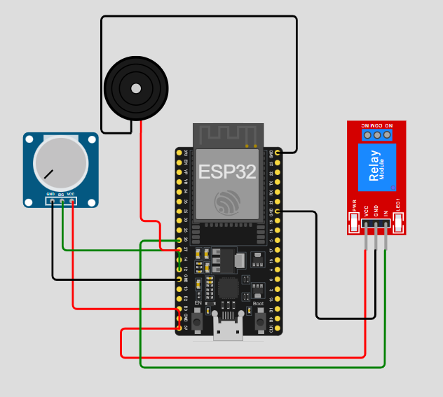
SCHEMATIC CONNECTION

Connect potentiometer:

  • Connect the VCC pin of the potentiometer to the 5V pin of the ESP32.
  • Connect the GND pin of the potentiometer to the GND pin of the ESP32.
  • Connect the Sig pin of the potentiometer to the 12 pin of the ESP32.
  • Connect buzzer:

  • Connect the +ve pin of the buzzer to the 27 pin of the ESP32
  • Connect the -ve pin of the buzzer to the GND pin of the ESP32.
  • Connect Relay :

  • Connect the 26 pin of the ESP32 to the IN pin of the relay module.
  • Connect the 5v pin of the ESP32 to the VCC pin of the relay module .
  • Connect the Gnd pin of the ESP32 to the GND pin of the relay module .
  • To begin your project, click this template link:

    Simulate on Wokwi

    ARDUINO CODE


    const int soilMoisturePin = 12;   // Potentiometer simulating soil sensor
    const int pumpPin = 26;           // LED as pump
    const int buzzerPin = 27;         // Active buzzer
    const int moistureThreshold = 500;
    
    void setup() {
      pinMode(soilMoisturePin, INPUT);
      pinMode(pumpPin, OUTPUT);
      pinMode(buzzerPin, OUTPUT);
      Serial.begin(9600);
    }
    
    void loop() {
      int moistureLevel = analogRead(soilMoisturePin);
    
      Serial.print("Moisture level: ");
      Serial.println(moistureLevel);
    
      if (moistureLevel < moistureThreshold) {
        Serial.println("Soil too dry. Activating pump and buzzer...");
        
        digitalWrite(pumpPin, HIGH);
        digitalWrite(buzzerPin, HIGH);
        
        delay(5000);  // Simulate watering duration
        
        digitalWrite(pumpPin, LOW);
        digitalWrite(buzzerPin, LOW);
        
        Serial.println("Watering complete.");
      } else {
        Serial.println("Soil moisture level is adequate.");
        digitalWrite(pumpPin, LOW);
        digitalWrite(buzzerPin, LOW);
      }
    
      delay(1000);  // Delay between checks
    }


    INSTRUCTIONS

  • Assemble the circuit by connecting all components as shown in the schematic diagram.
  • On the left side of the screen, open sketch.ino and write your Arduino code.
  • After completing the circuit and writing the code, click the green Play button to start the simulation.
  • The system uses a soil moisture sensor to read moisture levels continuously. If the reading falls below 500, it activates a buzzer and turns on the pump; otherwise, both remain off.
  • WORKING PRINCIPLE

  • The ESP32 reads data from the soil moisture sensor to assess the dryness of the soil. When the moisture level drops below 500, it triggers the buzzer and activates the water pump to irrigate the plant.

  • Project Link

    for your reference.

    `