
Smart parking system using ultrasonic sensor ,ir sensor, Servo using wokwi simulations ,
OBJECTIVE
The objective of this project is to detect car presence in parking slots and display whether each slot is free or occupied on an LCD screen.
MODULES REQUIRED
- Arduino uno
- Ultrasonic sensor
- Red led
- Green led
- Breadboard
- Servo
- Resistor 220ohm
- IR receiver
- Potentiometer
SCHEMATIC DIAGRAM
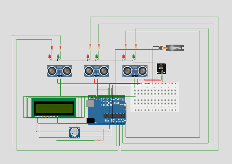
SCHEMATIC CONNECTION
Power Distribution:
LCD 16x2 Display:
Potentiometer (for LCD Contrast):
Ultrasonic Sensors (for 3 Parking Slots):
Sensor 1 (Left):
- VCC to the 5V rail..
- GND to the GND rail.
- Trig & Echo pins are connected together and then to Arduino Digital Pin 10.
Sensor 2 (Middle):
- VCC to the 5V rail.
- GND to the GND rail.
- Trig & Echo pins are connected together and then to Arduino Digital Pin 9.
Sensor 3 (Right):
- VCC to the 5V rail.
- GND to the GND rail.
- Trig & Echo pins are connected together and then to Arduino Digital Pin 8.
Indicator LEDs (for 3 Parking Slots)
Slot 1 LEDs:
- Green LED: Anode (+) to a 220Ω resistor, other end of the resistor to Arduino Analog Pin A0. Cathode (-) to GND.
- Red LED: Anode (+) to a 220Ω resistor, other end of the resistor to Arduino Analog Pin A1. Cathode (-) to GND
Slot 2 LEDs:
- Green LED: Anode (+) to a 220Ω resistor, other end of the resistor to Arduino Analog Pin A2. Cathode (-) to GND.
- Red LED: Anode (+) to a 220Ω resistor, other end of the resistor to Arduino Analog Pin A3. Cathode (-) to GND.
Slot 3 LEDs:
- Green LED: Anode (+) to a 220Ω resistor, other end of the resistor to Arduino Analog Pin A4. Cathode (-) to GND.
- Red LED: Anode (+) to a 220Ω resistor, other end of the resistor to Arduino Analog Pin A5. Cathode (-) to GND
Servo Motor (Gate Control)
- Signal wire (Orange/Yellow) to Arduino Digital Pin 6.
- VCC wire (Red) to the 5V rail.
- GND wire (Brown/Black) to the GND rail.
IR Sensor Vehicle Detection at Entrance
- OUT (Signal) pin to Arduino Digital Pin 7.
- VCC pin to the 5V rail.
- GND pin to the GND rail.
To begin your project, click this template link:
ARDUINO CODE
#include (LiquidCrystal.h)
#include (Servo.h)

LiquidCrystal lcd(12, 11, 5, 4, 3, 2);

#define t1 10
#define t2 9
#define t3 8

#define IR_SENSOR_PIN 7
#define SERVO_PIN 6

#define GREEN_LED1 A0
#define GREEN_LED2 A2
#define GREEN_LED3 A4

#define RED_LED1 A1
#define RED_LED2 A3
#define RED_LED3 A5

Servo servoMotor;
int distanceThreshold = 150;

void setup() {
  lcd.begin(16,2);
  lcd.setCursor(0,0);

  pinMode(IR_SENSOR_PIN, INPUT_PULLUP);

  pinMode(GREEN_LED1, OUTPUT);
  pinMode(GREEN_LED2, OUTPUT);
  pinMode(GREEN_LED3, OUTPUT);

  pinMode(RED_LED1, OUTPUT);
  pinMode(RED_LED2, OUTPUT);
  pinMode(RED_LED3, OUTPUT);

  servoMotor.attach(SERVO_PIN);

  Serial.begin (9600);
}

long readDistance(int triggerPin, int echoPin) {

  pinMode(triggerPin, OUTPUT);
  digitalWrite(triggerPin, LOW);
  delayMicroseconds(2);
  digitalWrite(triggerPin, HIGH);
  delayMicroseconds(10);
  digitalWrite(triggerPin, LOW);
  pinMode(echoPin, INPUT);
  return pulseIn(echoPin, HIGH);
}

void handleLEDs(float distance, int greenLedPin, int redLedPin) {
  if (distance >= distanceThreshold){
    digitalWrite(greenLedPin, HIGH);
    digitalWrite(redLedPin, LOW);
    Serial.println("Empty slot!!");
  } else {
    digitalWrite(redLedPin, HIGH);
    digitalWrite(greenLedPin, LOW);
    Serial.println("Car is parked");
  }
}

void loop() {
  //... same code as above ...
  float d1 = 0.01723 * readDistance(t1, t1);
  float d2 = 0.01723 * readDistance(t2, t2);
  float d3 = 0.01723 * readDistance(t3, t3);

  Serial.println("d1 = " + String(d1) + "cm");
  Serial.println("d2 = " + String(d2) + "cm");
  Serial.println("d3 = " + String(d3) + "cm");

  if (digitalRead(IR_SENSOR_PIN) == LOW) { // Vehicle detected by IR sensor
    if (d1 > 100 || d2 > 100 || d3 > 100) {
      servoMotor.write(90); // Assuming 90 degrees opens the gate
      delay(500);
      servoMotor.write(0); // Assuming 0 degrees closes the gate after some time
      delay(500);
    } else {
      // Do nothing or maybe sound a buzzer to indicate parking full
    }
  }

  // Handle LEDs based on the distance readings
  handleLEDs(d1, GREEN_LED1, RED_LED1);
  handleLEDs(d2, GREEN_LED2, RED_LED2);
  handleLEDs(d3, GREEN_LED3, RED_LED3);

if (d1>100 & d2>100 & d3>100){
  lcd.setCursor(0,0);
  lcd.print("3 Slots Free");
  lcd.setCursor(0,1);
  lcd.print("Slot 1 2 3 Free");
  delay(500);
  }
else if((d1>100 & d2>100)|(d2>100 & d3>100)|(d3>100 & d1>100))
  {
  lcd.setCursor(0,0);
  lcd.print("2 Slots Free");
  lcd.setCursor(0,1);
    if(d1>100 & d2>100)
    lcd.print("Slot 1 & 2 Free");
    else if(d1>100 & d3>100)
    lcd.print("Slot 1 & 3 Free");
    else
    lcd.print("Slot 2 & 3 Free");
  delay(500);
  }
else if(d1<100 & d2<100 & d3<100)
  {
  lcd.setCursor(0,0);
  lcd.print("No Slot Free");
  lcd.setCursor(0,1);
  lcd.print("Parking Full");
  delay(500);
  }
else if((d1<100 & d2<100)|(d2<100 & d3<100)|(d3<100 & d1<100))
  {
  lcd.setCursor(0,0);
  lcd.print("1 Slot Free");
  lcd.setCursor(0,1);
    if(d1>100)
      lcd.print("Slot 1 is Free");
    else if (d2>100)
       lcd.print("Slot 2 is Free");
    else
       lcd.print("Slot 3 is Free");
  delay(500);
   }
  delay(100);
}