A modern technology banner image

ESP32-Based Manual Relay Control System using Push Buttons

OBJECTIVE

To develop an ESP32-based system that enables manual switching of four electrical loads using separate push buttons, each linked to a corresponding relay.

MODULES REQUIRED

  • Esp-32
  • 4 push buttons
  • 4 relays
  • 4 leds

SCHEMATIC DIAGRAM

Schematic diagram showing an Arduino connected to an LED and a push button.

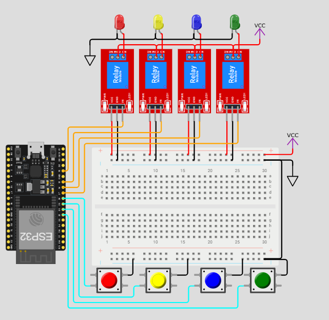
SCHEMATIC CONNECTION

Connect Relay 1 :

  • Connect the breadboard + (positive) rail to the VCC pin on the relay module.
  • Connect the breadboard - (Negative) rail to the GND pin on the relay module.
  • Connect the D13 pin of the ESP32 to the IN pin on the relay module.
  • Connect Relay 2 :

  • Connect the breadboard + (positive) rail to the VCC pin on the relay module.
  • Connect the breadboard - (Negative) rail to the GND pin on the relay module.
  • Connect the D12 pin of the ESP32 to the IN pin on the relay module.
  • Connect Relay 3 :

  • Connect the breadboard + (positive) rail to the VCC pin on the relay module.
  • Connect the breadboard - (Negative) rail to the GND pin on the relay module.
  • Connect the D14 pin of the ESP32 to the IN pin on the relay module.
  • Connect Relay 4 :

  • Connect the breadboard + (positive) rail to the VCC pin on the relay module.
  • Connect the breadboard - (Negative) rail to the GND pin on the relay module.
  • Connect the D27 pin of the ESP32 to the IN pin on the relay module.
  • Connect push buttons:

  • Connect the positive terminal of the push button to GPIO26 (pin 26) on the ESP32.
  • Connect the breadboard – (negative) rail to the GND pin on the push button.
  • Connect the positive terminal of the push button to GPIO25 (pin 25) on the ESP32.
  • Connect the breadboard – (negative) rail to the GND pin on the push button.
  • Connect the positive terminal of the push button to GPIO33 (pin 33) on the ESP32.
  • Connect the breadboard – (negative) rail to the GND pin on the push button.
  • Connect the positive terminal of the push button to GPIO32 (pin 32) on the ESP32.
  • Connect the breadboard – (negative) rail to the GND pin on the push button.
  • Connect leds:

  • Connect the +V pin (anode) of the LED to the NO (Normally Open) pin on the relay.
  • Connect the –V pin (cathode) of the LED to the negative rail on the breadboard.
  • Connect the COM (Common) pin of each relay together using jumper wires to form a common connection.
  • Same like the others connections .
  • To begin your project, click this template link:

    Simulate on Wokwi

    ARDUINO CODE


    #define button1_pin 26
    #define button2_pin 25
    #define button3_pin 33
    #define button4_pin 32
    
    #define relay1_pin 13
    #define relay2_pin 12
    #define relay3_pin 14
    #define relay4_pin 27
    
    int relay1_state = 0;
    int relay2_state = 0;
    int relay3_state = 0;
    int relay4_state = 0;
    
    void setup() {
      // put your setup code here, to run once:
      Serial.begin(115200);
      Serial.println("Hello, ESP32!");
    
      //--------------------------------------------------------------------
      pinMode(button1_pin, INPUT_PULLUP);
      pinMode(button2_pin, INPUT_PULLUP);
      pinMode(button3_pin, INPUT_PULLUP);
      pinMode(button4_pin, INPUT_PULLUP);
      //--------------------------------------------------------------------
      pinMode(relay1_pin, OUTPUT);
      pinMode(relay2_pin, OUTPUT);
      pinMode(relay3_pin, OUTPUT);
      pinMode(relay4_pin, OUTPUT);
      //--------------------------------------------------------------------
      //During Starting all Relays should TURN OFF
      digitalWrite(relay1_pin, LOW);
      digitalWrite(relay2_pin, HIGH);
      digitalWrite(relay3_pin, LOW);
      digitalWrite(relay4_pin, HIGH);
    }
    
    void loop() {
      // put your main code here, to run repeatedly:
      listen_push_buttons();
      delay(10); // this speeds up the simulation
    }
    
    void listen_push_buttons(){
        //--------------------------------------------------------------------------
        if(digitalRead(button1_pin) == LOW){
          delay(200);
          control_relay(1);
        }
        //--------------------------------------------------------------------------
        else if (digitalRead(button2_pin) == LOW){
          delay(200);
          control_relay(2);
        }
        //--------------------------------------------------------------------------
        else if (digitalRead(button3_pin) == LOW){
          delay(200);
          control_relay(3);
        }
        //--------------------------------------------------------------------------
        else if (digitalRead(button4_pin) == LOW){
          delay(200);
          control_relay(4);
        } 
        //--------------------------------------------------------------------------
    }
    
    void control_relay(int relay){
      //------------------------------------------------
      if(relay == 1){
        relay1_state = !relay1_state;
        digitalWrite(relay1_pin, relay1_state);
        Serial.print("Button1 State = ");
        Serial.println(digitalRead(button1_pin));
        Serial.print("Relay1 State = ");
        Serial.println(relay1_state);
        delay(50);
      }
      //------------------------------------------------
      else if(relay == 2){
        relay2_state = !relay2_state;
        digitalWrite(relay2_pin, relay2_state);
        Serial.print("Relay2 State = ");
        Serial.println(relay2_state);
    
        delay(50);
      }
      //------------------------------------------------
      else if(relay == 3){
        relay3_state = !relay3_state;
        digitalWrite(relay3_pin, relay3_state);
        Serial.print("Relay3 State = ");
        Serial.println(relay3_state);
        delay(50);
      }
      //------------------------------------------------
      else if(relay == 4){
        relay4_state = !relay4_state;
        digitalWrite(relay4_pin, relay4_state);
        Serial.print("Relay4 State = ");
        Serial.println(relay4_state);
        delay(50);
      }
      //------------------------------------------------
    }


    INSTRUCTIONS

  • Assemble the circuit by connecting all components as shown in the schematic diagram.
  • On the left side of the screen, open sketch.ino and write your Arduino code.
  • After completing the circuit and writing the code, click the green Play button to start the simulation.
  • On startup, all relays are initialized to OFF; the loop continuously monitors button presses, applies a short debounce delay, toggles the corresponding relay state, and displays the updated state on the serial monitor.
  • WORKING PRINCIPLE

  • Each of the four push buttons is assigned to control one relay. When a button is pressed, the corresponding relay toggles its ON/OFF state. The current state is tracked using variables and printed via the serial monitor.

  • Project Link

    for your reference.

    `