A modern technology banner image

LDR-based Smart Street Light Simulation on Wokwi

OBJECTIVE

To design a smart street lighting system using an LDR sensor and Arduino that automatically turns ON 4 street lights (LEDs) when it gets dark, and turns them OFF during daylight.

MODULES REQUIRED

  • Arduino uno
  • Ldr sensor
  • LED (4)

SCHEMATIC DIAGRAM

Schematic diagram showing an Arduino connected to an LED and a push button.

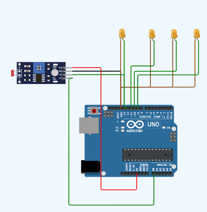
SCHEMATIC CONNECTION

Connect LDR:

  • Connect the VCC pin of the Ldr to the 5v pin on the Arduino .
  • Connect the GND pin of the Ldr to the GND pin on the Arduino .
  • Connect the A0 pin of the Ldr to the A0 pin on the Arduino.
  • Connect the D0 pin of the Ldr to the D13 pin on the Arduino.
  • Connect leds:

  • Connect the +ve pin of the led1 to the D12 pin on the Arduino .
  • Connect the -ve pin of the led1 to the Gnd pin on the Arduino.
  • Connect the +ve pin of the led2 to the D11 pin on the Arduino.
  • Connect the -ve pin of the led 2 to the Gnd pin on the Arduino.
  • Connect the +ve pin of the led 3 to the D10 pin on the Arduino.
  • Connect the -ve pin of the led 3 to the Gnd pin on the Arduino.
  • Connect the +ve pin of the led 4 to the D9 pin on the Arduino .
  • Connect the -ve pin of the led 4 to the Gnd pin on the Arduino .
  • To begin your project, click this template link:

    Simulate on Wokwi

    ARDUINO CODE

    
    #const int ldrpin = 13;
    const int led1 = 12;
    const int led2 = 11;
    const int led3 = 10;
    const int led4 = 9;
    
    void setup() {
      pinMode(ldrpin, INPUT);
      pinMode(12, OUTPUT);
      pinMode(11, OUTPUT);
      pinMode(10, OUTPUT);
      pinMode(9, OUTPUT);
    }
    void loop() {
      int data=digitalRead(ldrpin);
      if (data == 0){
        digitalWrite(12, HIGH);
        digitalWrite(11, HIGH);
        digitalWrite(10, HIGH);
        digitalWrite(9, HIGH);
      }
      else{
        digitalWrite(12, LOW);
        digitalWrite(11, LOW);
        digitalWrite(10, LOW);
        digitalWrite(9, LOW);
      }
    }


    INSTRUCTIONS

  • Assemble the circuit by connecting all components as shown in the schematic diagram.
  • On the left side of the screen, open sketch.ino and write your Arduino code.
  • After completing the circuit and writing the code, click the green Play button to start the simulation.
  • This smart street lighting system uses an LDR sensor and Arduino to detect light levels, adjusting LED states based on a threshold to turn ON in darkness and OFF in daylight.
  • WORKING PRINCIPLE

  • The smart street lighting system uses an LDR sensor and Arduino to detect light levels and automatically control 4 LEDs to turn ON in darkness and OFF in daylight.

  • Project Link

    for your reference.

    `