A modern technology banner image

Smart Garage Door ESP-32

OBJECTIVE

This project builds a Smart Garage Door using ESP32 for wireless control, demonstrating IoT-based motor control and sensor integration for secure remote access.

MODULES REQUIRED

  • Esp-32
  • Pir motion
  • Servo
  • Led

SCHEMATIC DIAGRAM

Schematic diagram showing an Arduino connected to an LED and a push button.

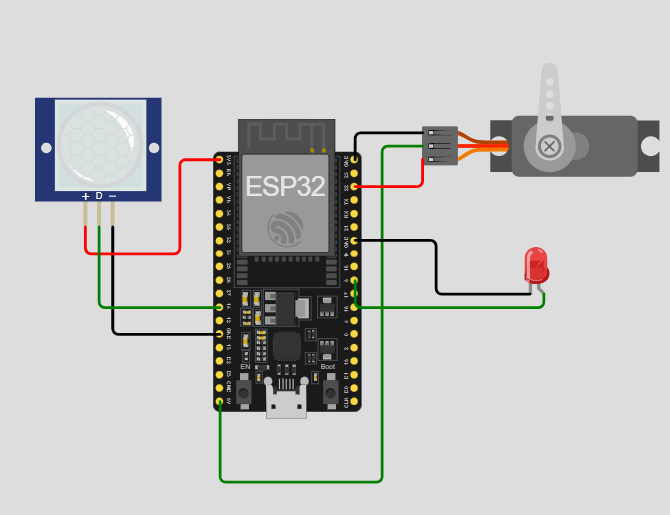
SCHEMATIC CONNECTION

Connect pir :

  • Connect the D pin of the PIR sensor to GPIO14 (pin 14) of the ESP32.
  • Connect the +V (VCC) pin of the PIR sensor to the 3.3V pin of the ESP32.
  • Connect the -V(GND ) pin of the PIR sensor to the GND pin of the ESP32.
  • Connect servo:

  • Connect the servo V+(VCC ) to the 5V pin on the ESP32.
  • Connect the servo GND to the GND pin on the ESP32.
  • Connect the servo pwm to the GPIO22 (22pin ) on the ESP32
  • Connect LED:

  • Connect the led anode (+ve) to the GPIO 5 (5 pin ) on the ESP32.
  • Connect the led cathode(-ve) to the GND pin on the ESP32.
  • To begin your project, click this template link:

    Simulate on Wokwi

    ARDUINO CODE


    #include (ESP32Servo.h) // Servo library for ESP32
    
    // Pin definitions
    #define PIR_PIN 14       // PIR sensor pin
    #define SERVO_PIN 22     // Servo motor pin
    #define LED_PIN 5        // LED indicator pin
    
    Servo doorServo;         // Servo object for the door
    
    void setup() {
      Serial.begin(115200);            // Initialize Serial Monitor
      doorServo.attach(SERVO_PIN);     // Attach servo to pin
      pinMode(PIR_PIN, INPUT);         // Set PIR as input
      pinMode(LED_PIN, OUTPUT);        // Set LED as output
      doorServo.write(0);              // Initial servo position (closed)
      digitalWrite(LED_PIN, LOW);      // LED off at start
      Serial.println("System Ready");
    }
    
    void loop() {
      int motionDetected = digitalRead(PIR_PIN); // Read PIR sensor
    
      if (motionDetected == HIGH) {      // If motion is detected
        Serial.println("Opening door...");
    
        doorServo.write(180);            // Open door
        digitalWrite(LED_PIN, HIGH);     // LED on
        delay(1000);                     // Keep open for 1 second
    
        Serial.println("Closing door...");
        doorServo.write(0);              // Close door
        delay(1000);                     // Wait for door to close
        digitalWrite(LED_PIN, LOW);      // LED off
    
        delay(2000);                     // Avoid immediate retriggering
        Serial.println("System Reset");
      }
      delay(500);                        // Check sensor periodically
    }


    INSTRUCTIONS

  • Assemble the circuit by connecting all components as shown in the schematic diagram.
  • On the left side of the screen, open sketch.ino and write your Arduino code.
  • After completing the circuit and writing the code, click the green Play button to start the simulation.
  • The system operates on the principle of motion detection triggering an automated response. The ESP32 senses motion, activates the door and LED, and then closes the door after a predetermined delay.
  • WORKING PRINCIPLE

  • The system operates on the principle of motion detection triggering an automated response. When motion is sensed, the ESP32 activates the door and LED, then closes the door after a timed delay.

  • Project Link

    for your reference.

    `