
DIY Digital clock temperature & Humidity sensor using simulation
OBJECTIVE
To design and simulate a DIY digital clock using a dot matrix display that shows real-time time, temperature, and humidity readings with the help of a temperature and humidity sensor.
MODULES REQUIRED
- Arduino uno
- Led Dot matrix (MAX7219)
- DHT22
- DS1307 RTC
SCHEMATIC DIAGRAM
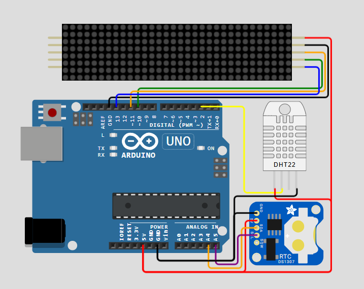
SCHEMATIC CONNECTION
Connect 4 digit display:
Connect Dht22:
Connect RTC:
To begin your project, click this template link:
ARDUINO CODE
#include (MD_Parola.h)
#include (MD_MAX72xx.h)
#include (DHT.h)
#include (SPI.h)
#include (Wire.h)
#include "Font7Seg.h"

// Define the number of devices we have in the chain and the hardware interface
// NOTE: These pin numbers will probably not work with your hardware and may
// need to be adapted
#define HARDWARE_TYPE MD_MAX72XX::PAROLA_HW
#define MAX_DEVICES 4 // Define the number of displays connected
#define CLK_PIN    13 // CLK or SCK
#define DATA_PIN   11 // DATA or MOSI
#define CS_PIN     10 // CS or SS
#define SPEED_TIME 75 // Speed of the transition
#define PAUSE_TIME  0
#define MAX_MESG   20

// These are for the clock
#define DS1307_ADDRESS 0x68

// These are for the temperature
#define DHTPIN 2
#define DHTTYPE DHT22
#define TIMEDHT 1000

// Global variables
uint8_t wday, mday, month, year;
uint8_t hours, minutes, seconds;

char szTime[9];    // mm:ss\0
char szMesg[MAX_MESG + 1] = "";

float humidity, celsius, fahrenheit;

uint8_t degC[] = { 6, 3, 3, 56, 68, 68, 68 }; // Deg C
uint8_t degF[] = { 6, 3, 3, 124, 20, 20, 4 }; // Deg F

uint8_t clear = 0x00;

uint32_t timerDHT = TIMEDHT;

DHT dht(DHTPIN, DHTTYPE);

// Hardware SPI connection
MD_Parola P = MD_Parola(HARDWARE_TYPE, CS_PIN, MAX_DEVICES);

void beginDS1307()
{
  // Read the values (date and time) of the DS1307 module
  Wire.beginTransmission(DS1307_ADDRESS);
  Wire.write(clear);
  Wire.endTransmission();
  Wire.requestFrom(DS1307_ADDRESS, 0x07);

  seconds = bcdToDec(Wire.read());
  minutes = bcdToDec(Wire.read());
  hours = bcdToDec(Wire.read() & 0xff);
  wday = bcdToDec(Wire.read());
  mday = bcdToDec(Wire.read());
  month = bcdToDec(Wire.read());
  year = bcdToDec(Wire.read());
}

uint8_t decToBcd(uint8_t value)
{
  return ((value / 10 * 16) + (value % 10));
}

uint8_t bcdToDec(uint8_t value)
{
  return ((value / 16 * 10) + (value % 16));
}

// Code for reading clock time
void getTime(char *psz, bool f = true)
{
  sprintf(psz, "%02d%c%02d", hours, (f ? ':' : ' '), minutes);
}

// Code for reading clock date
void getDate(char *psz)
{
  char  szBuf[10];
  sprintf(psz, "%d %s %04d", mday , mon2str(month, szBuf, sizeof(szBuf) - 1), (year + 2000));
}

// Code for get Temperature
void getTemperature()
{
  // Wait for a time between measurements
  if ((millis() - timerDHT) > TIMEDHT) {
    // Update the timer
    timerDHT = millis();

    // Reading temperature or humidity takes about 250 milliseconds!
    // Sensor readings may also be up to 2 seconds 'old' (its a very slow sensor)
    humidity = dht.readHumidity();

    // Read temperature as Celsius (the default)
    celsius = dht.readTemperature();

    // Read temperature as Fahrenheit (isFahrenheit = true)
    fahrenheit = dht.readTemperature(true);

    // Check if any reads failed and exit early (to try again)
    if (isnan(humidity) || isnan(celsius) || isnan(fahrenheit)) {
      Serial.println("Failed to read from DHT sensor!");
      return;
    }
  }
}

// Get a label from PROGMEM into a char array
char *mon2str(uint8_t mon, char *psz, uint8_t len)
{
  static const __FlashStringHelper* str[] =
  {
    F("Jan"), F("Feb"), F("Mar"), F("Apr"),
    F("May"), F("Jun"), F("Jul"), F("Aug"),
    F("Sep"), F("Oct"), F("Nov"), F("Dec")
  };

  strncpy_P(psz, (const char PROGMEM *)str[mon - 1], len);
  psz[len] = '\0';

  return (psz);
}

char *dow2str(uint8_t code, char *psz, uint8_t len)
{
  static const __FlashStringHelper* str[] =
  {
    F("Sunday"), F("Monday"), F("Tuesday"),
    F("Wednesday"), F("Thursday"), F("Friday"),
    F("Saturday")
  };

  strncpy_P(psz, (const char PROGMEM *)str[code - 1], len);

  psz[len] = '\0';

  return (psz);
}

void setup(void)
{
  Wire.begin();

  P.begin(2);
  P.setInvert(false);

  P.setZone(0,  MAX_DEVICES - 4, MAX_DEVICES - 1);
  P.setZone(1, MAX_DEVICES - 4, MAX_DEVICES - 1);

  P.displayZoneText(1, szTime, PA_CENTER, SPEED_TIME, PAUSE_TIME, PA_PRINT, PA_NO_EFFECT);
  P.displayZoneText(0, szMesg, PA_CENTER, SPEED_TIME, 0, PA_PRINT , PA_NO_EFFECT);

  P.addChar('$', degC);
  P.addChar('&', degF);

  dht.begin();
}

void loop(void)
{
  static uint32_t lastTime = 0; // Memory (ms)
  static uint8_t  display = 0;  // Current display mode
  static bool flasher = false;  // Seconds passing flasher

  beginDS1307();
  getTemperature();

  P.displayAnimate();

  if (P.getZoneStatus(0))
  {
    switch (display)
    {
    case 0: // Temperature deg Celsius
      P.setPause(0, 1000);
      P.setTextEffect(0, PA_SCROLL_LEFT, PA_SCROLL_UP);
      display++;
      dtostrf(celsius, 3, 1, szMesg);
      strcat(szMesg, "$");

      break;
    case 1: // Temperature deg Fahrenheit
      P.setTextEffect(0, PA_SCROLL_UP, PA_SCROLL_DOWN);
      display++;
      dtostrf(fahrenheit, 3, 1, szMesg);
      strcat(szMesg, "&");

      break;
    case 2: // Humidity
      P.setTextEffect(0, PA_SCROLL_DOWN, PA_SCROLL_LEFT);
      display++;
      dtostrf(humidity, 3, 0, szMesg);
      strcat(szMesg, "%UR");

      break;
    case 3: // Clock
      P.setFont(0, numeric7Seg);
      P.setTextEffect(0, PA_PRINT, PA_NO_EFFECT);
      P.setPause(0, 0);

      if ((millis() - lastTime) >= 1000)
      {
        lastTime = millis();
        getTime(szMesg, flasher);
        flasher = !flasher;
      }

      if ((seconds == 00) && (seconds <= 30)) {
        display++;
        P.setTextEffect(0, PA_PRINT, PA_WIPE_CURSOR);
      }

      break;
    case 4: // Day of week
      P.setFont(0, nullptr);
      P.setTextEffect(0, PA_SCROLL_LEFT, PA_SCROLL_LEFT);
      display++;
      dow2str(wday, szMesg, MAX_MESG);

      break;
    default: // Calendar
      P.setTextEffect(0, PA_SCROLL_LEFT, PA_SCROLL_LEFT);
      display = 0;
      getDate(szMesg);

      break;
    }

    P.displayReset(0); // Rest zone zero
  }
}