
Arduino Based Digital Alarm Clock
OBJECTIVE
To design a cost-effective, user-friendly digital alarm clock using Arduino that displays real-time via an RTC module, allows alarm setting through push buttons, and triggers an audible alert using a buzzer.
MODULES REQUIRED
- Arduino uno
- Lcd Display 16 x 2
- RTC DS1307
- Push buttons
- buzzer
SCHEMATIC DIAGRAM
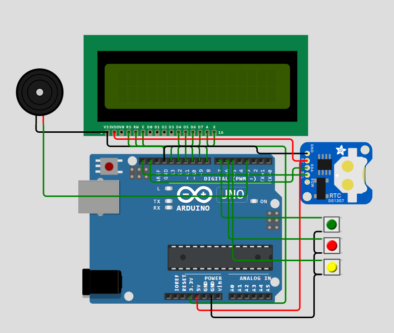
SCHEMATIC CONNECTION
Connect Lcd:
Connect RTC:
Connect buzzer:
Connect push button :
To begin your project, click this template link:
ARDUINO CODE
#include (Wire.h)
#include (EEPROM.h)
#include (RTClib.h)
#include (LiquidCrystal.h)

// Pin configuration for LCD
const int rs = 8;
const int en = 9;
const int d4 = 10;
const int d5 = 11;
const int d6 = 12;
const int d7 = 13;

LiquidCrystal lcd(rs, en, d4, d5, d6, d7);  // LCD initialization
RTC_DS1307 RTC;  // RTC object

// Pin configuration for buttons and buzzer
int INC = 6;      // Increment button
int next = 7;     // Next button
int set_mad = 5;  // Set alarm button
#define buzzer 3   // Buzzer pin

int HOUR, MINUT, SECOND;  // Variables to store time
int hours1, minut, add = 11;  // Alarm time variables

void setup() {
  Wire.begin();
  RTC.begin();
  lcd.begin(16, 2);  // Initialize LCD with 16 columns and 2 rows

  pinMode(INC, INPUT);
  pinMode(next, INPUT);
  pinMode(set_mad, INPUT);
  pinMode(buzzer, OUTPUT);  // Set buzzer as output

  digitalWrite(next, HIGH);
  digitalWrite(set_mad, HIGH);
  digitalWrite(INC, HIGH);

  lcd.setCursor(0, 0);
  lcd.print("Real Time Clock");
  lcd.setCursor(0, 1);
  lcd.print("By Circuit Digest");
  delay(2000);

  // Adjust RTC if not running
  if (!RTC.isrunning()) {
    RTC.adjust(DateTime(__DATE__, __TIME__));
  }
}

void loop() {
  DateTime now = RTC.now();  // Get the current time from the RTC

  // Check if the 'set_mad' button is pressed to set the alarm time
  if (digitalRead(set_mad) == 0) {
    lcd.clear();
    lcd.setCursor(0, 0);
    lcd.print("  Set Alarm  ");
    delay(2000);
    set_alarm_time();
    delay(1000);
    lcd.clear();
    lcd.setCursor(0, 0);
    lcd.print("  Alarm time ");
    lcd.setCursor(0, 1);
    lcd.print(" has been set ");
    delay(2000);
  }

  // Display the current time
  lcd.clear();
  lcd.setCursor(0, 0);
  lcd.print("Time:");
  lcd.setCursor(6, 0);
  lcd.print(HOUR = now.hour(), DEC);
  lcd.print(":");
  lcd.print(MINUT = now.minute(), DEC);
  lcd.print(":");
  lcd.print(SECOND = now.second(), DEC);
  lcd.setCursor(0, 1);
  lcd.print("Date: ");
  lcd.print(now.day(), DEC);
  lcd.print("/");
  lcd.print(now.month(), DEC);
  lcd.print("/");
  lcd.print(now.year(), DEC);

  // Check if the current time matches the alarm time
  check_alarm_time();

  delay(200);
}

// Function to set the alarm time using the buttons
void set_alarm_time() {
  int temp = 1;
  int temp4;

  // Set the alarm hour
  while (temp == 1) {
    if (digitalRead(INC) == 0) {
      HOUR++;
      if (HOUR == 24) {
        HOUR = 0;
      }
      while (digitalRead(INC) == 0);  // Wait until button is released
    }

    lcd.clear();
    lcd.setCursor(0, 0);
    lcd.print("Set Alarm Time ");
    lcd.setCursor(0, 1);
    lcd.print(HOUR);
    lcd.print(":");
    lcd.print(MINUT);
    lcd.print(":");
    lcd.print(SECOND);
    delay(100);

    // Save the alarm hour when 'next' button is pressed
    if (digitalRead(next) == 0) {
      hours1 = HOUR;
      EEPROM.write(add++, hours1);  // Store hour in EEPROM
      temp = 2;
      while (digitalRead(next) == 0);  // Wait until button is released
    }
  }

  // Set the alarm minute
  while (temp == 2) {
    if (digitalRead(INC) == 0) {
      MINUT++;
      if (MINUT == 60) {
        MINUT = 0;
      }
      while (digitalRead(INC) == 0);  // Wait until button is released
    }

    lcd.clear();
    lcd.setCursor(0, 0);
    lcd.print("Set Alarm Time ");
    lcd.setCursor(0, 1);
    lcd.print(HOUR);
    lcd.print(":");
    lcd.print(MINUT);
    lcd.print(":");
    lcd.print(SECOND);
    delay(100);

    // Save the alarm minute when 'next' button is pressed
    if (digitalRead(next) == 0) {
      minut = MINUT;
      EEPROM.write(add++, minut);  // Store minute in EEPROM
      temp = 0;
      while (digitalRead(next) == 0);  // Wait until button is released
    }
  }
}

// Function to check if the current time matches the alarm time
void check_alarm_time() {
  int alarm_hour = EEPROM.read(11);  // Read the stored alarm hour
  int alarm_minute = EEPROM.read(12);  // Read the stored alarm minute

  // Debugging output
  Serial.print("Current Time: ");
  Serial.print(HOUR);
  Serial.print(":");
  Serial.println(MINUT);
  Serial.print("Stored Alarm Time: ");
  Serial.print(alarm_hour);
  Serial.print(":");
  Serial.println(alarm_minute);

  // If the current time matches the alarm time, trigger the alarm
  if (HOUR == alarm_hour && MINUT == alarm_minute) {
    trigger_alarm();
  }
}

// Function to trigger the alarm (beep sound)
void trigger_alarm() {
  beep();
  lcd.clear();
  lcd.print("Wake Up........");
  lcd.setCursor(0, 1);
  lcd.print("Wake Up.......");

  beep();
  beep();
  beep();
}

// Function to make the buzzer beep
void beep() {
  tone(buzzer, 1000);  // Play tone at 1000 Hz
  delay(500);          // Wait for 500ms
  noTone(buzzer);      // Stop the tone
  delay(500);          // Wait for 500ms
}