A modern technology banner image

ESP-32 LED chaser using simulation

OBJECTIVE

The project aims to help beginners understand how to control multiple digital outputs using basic programming logic and timing functions in Arduino (ESP32).

MODULES REQUIRED

  • Esp-32
  • 12 x LEDS
  • 12 x 220ohm resistors

SCHEMATIC DIAGRAM

Schematic diagram showing an Arduino connected to an LED and a push button.

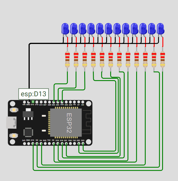
SCHEMATIC CONNECTION

Connection LED :

  • Connect the anode of LED1 to GPIO15 of the ESP32 through a current-limiting resistor.
  • Connect the anode of LED2 to GPIO2 of the ESP32 through a current-limiting resistor.
  • Connect the anode of LED3 to GPIO4 of the ESP32 through a current-limiting resistor
  • Connect the anode of LED4 to GPIO5 of the ESP32 through a current-limiting resistor
  • Connect the anode of LED5 to GPIO18 of the ESP32 through a current-limiting resistor
  • Connect the anode of LED6 to GPIO19 of the ESP32 through a current-limiting resistor
  • Connect the anode of LED7 to GPIO21 of the ESP32 through a current-limiting resistor
  • Connect the anode of LED8 to GPIO22 of the ESP32 through a current-limiting resistor
  • Connect the anode of LED9 to GPIO23 of the ESP32 through a current-limiting resistor
  • Connect the anode of LED10 to GPIO32 of the ESP32 through a current-limiting resistor
  • Connect the anode of LED11 to GPIO33 of the ESP32 through a current-limiting resistor
  • Connect the anode of LED12 to GPIO25 of the ESP32 through a current-limiting resistor
  • Connect the cathodes (–) of LED1 to LED12 to the GND pin of the ESP32.
  • To begin your project, click this template link:

    Simulate on Wokwi

    ARDUINO CODE


    //initializing a variable for digital pin 2 to 13
    int led1 = 15;
    int led2 = 2;
    int led3 = 4;
    int led4 = 5;
    int led5 = 18;
    int led6 = 19;
    int led7 = 21;
    int led8 = 22;
    int led9 = 23;
    int led10 = 32;
    int led11 = 33;
    int led12 = 25;
    
    void setup() {
      // put your setup code here, to run once:
     //initialize digital pin as output
     pinMode(led1, OUTPUT);
     pinMode(led2, OUTPUT);
     pinMode(led3, OUTPUT);
     pinMode(led4, OUTPUT);
     pinMode(led5, OUTPUT);
     pinMode(led6, OUTPUT);
     pinMode(led7, OUTPUT);
     pinMode(led8, OUTPUT);
     pinMode(led9, OUTPUT);
     pinMode(led10, OUTPUT);
     pinMode(led11, OUTPUT);
     pinMode(led12, OUTPUT);
    }
    
    void loop() {
      // put your main code here, to run repeatedly:
     digitalWrite(led1, HIGH);//it mean to give 5v(high) to pins.here ,the led will be on.
     delay(50);//1000 = 1 second
     digitalWrite(led2, HIGH);
     delay(50);
     digitalWrite(led3, HIGH);
     delay(50);
      digitalWrite(led4, HIGH);
     delay(50);
      digitalWrite(led5, HIGH);
     delay(50);
      digitalWrite(led6, HIGH);
     delay(50);
      digitalWrite(led7, HIGH);
     delay(50);
      digitalWrite(led8, HIGH);
     delay(50);
      digitalWrite(led9, HIGH);
     delay(50);
      digitalWrite(led10, HIGH);
     delay(50);
       digitalWrite(led11, HIGH);
     delay(50);
       digitalWrite(led12, HIGH);
     delay(50);
    
     digitalWrite(led1, LOW);//it mean to give 0v(low) to pin.here, led will be off
     delay(50);
     digitalWrite(led2, LOW);
     delay(50);
     digitalWrite(led3, LOW);
     delay(50);
     digitalWrite(led4, LOW);
     delay(50);
     digitalWrite(led5, LOW);
     delay(50);
     digitalWrite(led6, LOW);
     delay(50);
     digitalWrite(led7, LOW);
     delay(50);
     digitalWrite(led8, LOW);
     delay(50);
     digitalWrite(led9, LOW);
     delay(50);
     digitalWrite(led10, LOW);
     delay(50);
     digitalWrite(led11, LOW);
     delay(50);
     digitalWrite(led12, LOW);
     delay(50);
    }


    INSTRUCTIONS

  • Assemble the circuit by connecting all components as shown in the schematic diagram.
  • On the left side of the screen, open sketch.ino and write your Arduino code.
  • After completing the circuit and writing the code, click the green Play button to start the simulation.
  • This project teaches beginners how to control multiple LEDs using the ESP32 by applying simple programming logic. It also demonstrates the use of timing functions to create a sequential LED chaser effect.
  • WORKING PRINCIPLE

  • The ESP32 sequentially turns LEDs on and off using loops and delays, creating a forward and reverse chasing light effect.

  • Project Link

    for your reference.

    `